For actual project information, see MediaCow Touch 2 project page
Introduction
This is the first post of a series of blog posts about the development of MediaCow Touch 2 "Paris".
Background
MediaCow Touch 2 "Paris" is a project to build a tablet computer device using custom circuit design (PCBs). The idea existed since March 2021 with multiple attempts to design it in 2022. It was not until May-June 2024, I have made the commitment to the project.
Goals
My goal for the project is to have a working, physical prototype by August 26, 2024 when I return to Brightpoint Community College. The deadline that I gave to LattePanda in May was September 1, 2024.
The LattePanda Mu
On July 1, 2024, I received the LattePanda Mu System on Module (SoM) along with its Lite Carrier Board. I did not expect the LattePanda Mu to be as small as it is with a surface area smaller than Raspberry Pi format boards.
On July 2, 2024, I have assembled the carrier board with its acrylic plate and the LattePanda Mu. The module itself received the codename "Cyclobutane" which is the first codename I have assigned to development hardware. See Codename Guide for information on how and why I chose codenames for computer hardware.
When I booted up the LattePanda Mu, it was much more powerful than i expected it to be. It came with Windows 11 which I kept briefly to test gaming performance. This was the first time I ever used Windows 11 on my hardware and the first time I have used it for more than 5 minutes at a time.
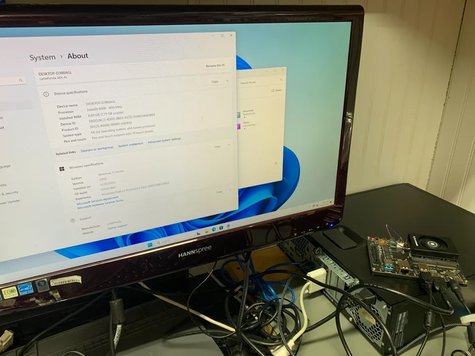
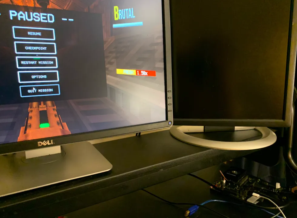
During this short period of time, I tested two games: ULTRAKILL and OneShot, which are realitively lightweight. Both games ran flawlessly at 60 FPS, ULTRAKILL ran better on the Intel N100 than the dual Intel Xeon X5670 and AMD Radeon RX 580 in "Polyethylene". OneShot's performance was not surprising since it is a top-down 2D game made with RPG Maker XP. This is great as all I originally expected out of MediaCow Touch 2 is a custom Android tablet that would just be used for messaging and web browsing. This is as a massive upgrade to the Rockchip RK3399 hardware I planned on using before.
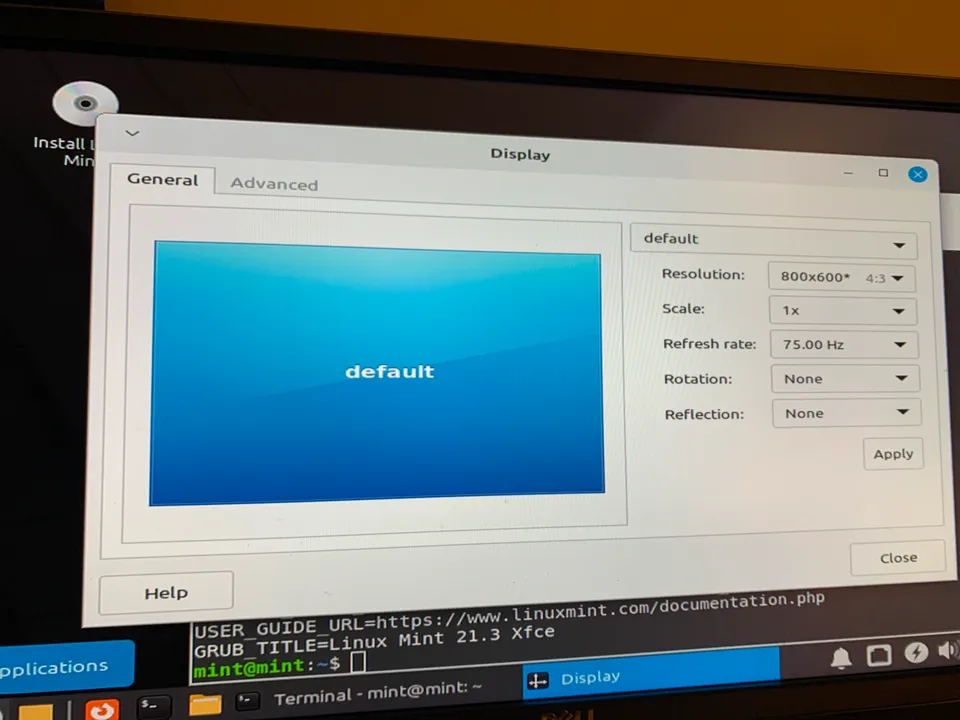
After some gaming, I decided to install Linux Mint 21.3 on the system to test its functionality under a Linux environment. In the live USB environment, the display resolution on HDMI was limited to 800x600, this is likely due to an older Linux kernel version on the live USB image. I presume it updated packages including the Linux kernel during the installation process since after rebooting, I could use a display resolution of 1920x1080.
Challenges and Subsystems
MediaCow Touch 2 is a highly ambitious project for someone with no formal education in the field and minimal experience with circuit design.
For more about each subsystem, see the project page for MediaCow Touch 2.
Circuit Design
Circuit design will be the most complex part of the design by far and is what is expected to take the most amount of time.
High Frequency
One thing I did not consider before going into the project is that I would have to work with many high-frequency differential connections. I do not have the equipment nor I would have any reasonable ability to access equipment that can debug such high frequency interfaces. This includes HDMI, DisplayPort, USB 3.0, PCIe 3.0 and MIPI CSI.
Display
As a size comparison, I looked at my Samsung XE500C13 Chromebook ("Chromium Sulfate") that also has an 11.6" display and determined that 11.6" is well sutable for the project. I have already used a 7" display in MediaCow Touch (1) "Nashville" and it seemed too small.i
On July 5, 2024, I received the 11.6" display, this allowed me to be able to get the measurement of the distance between the eDP connector and the horizontal edge of the display. When I received the display, I found out that it came with an non-FPC (flat cable) eDP cable that had it so that the location of the connector on the display is not critical for the layout of the carrier PCB. However, this measurement was still required to be able to add a cutout in the LCD holder part for the eDP and touchscreen connector.
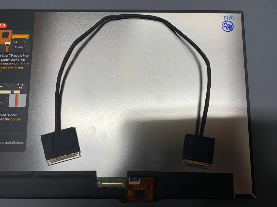
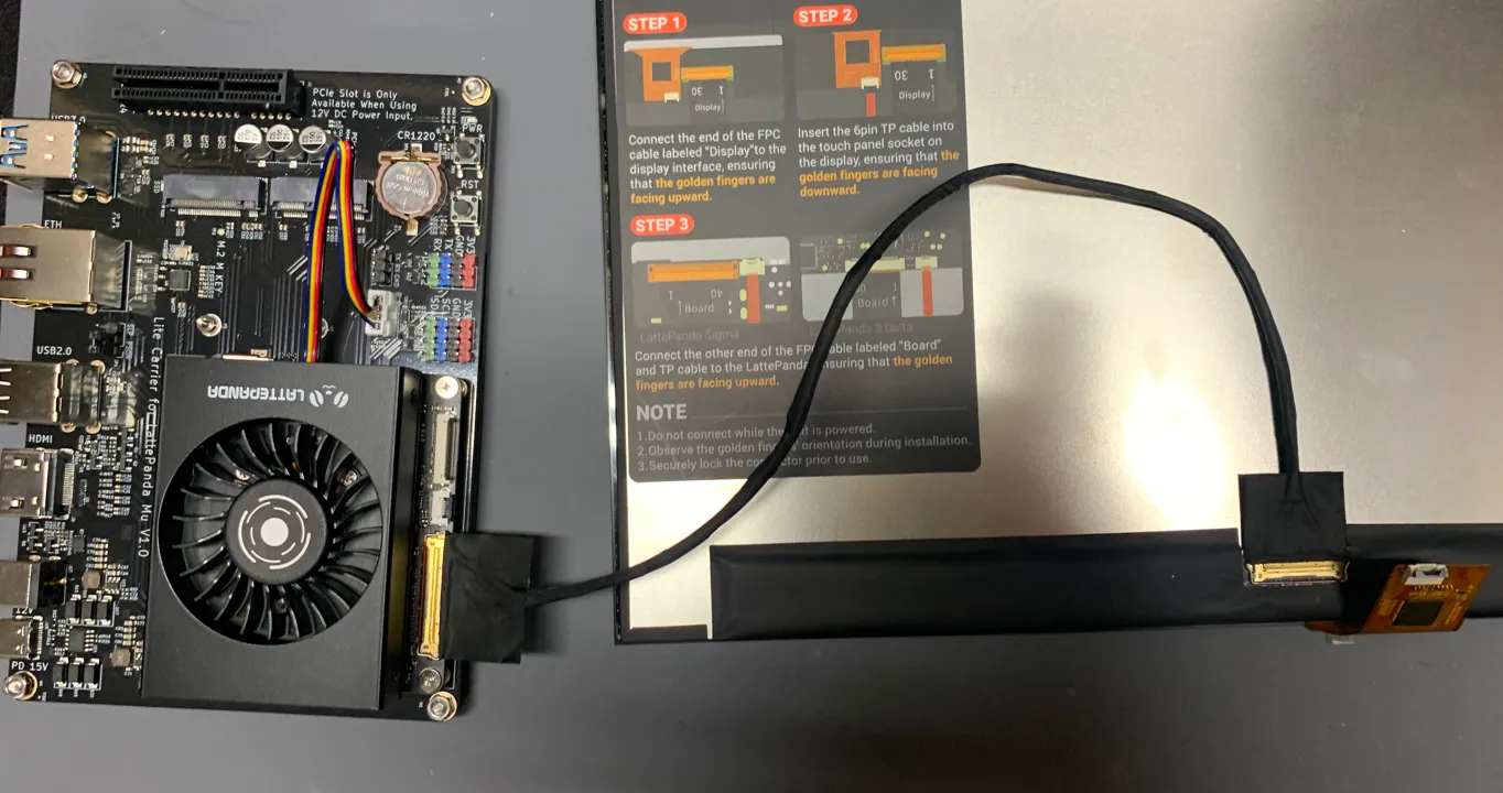
On July 9, 2024, I have tested the display for the first time. Under Linux Mint 21.3, the display was functional though there was no touch support though the addition of a kernel driver can fix that. Another thing I noticed is that the physical size of the display was not being reported. The size of the display not being reported had the system default to 96 DPI which is almost half of the display's actual DPI (~189.91 DPI), resulting in elements on screen being small.
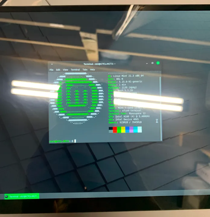
The display looked better than I expected though colors are as not as good as on many of the LCDs that I have used before. It is similar to the Apple iPhone XR that I use exclusively for social media and research. Overall, the display is better than the one used in the former MediaCow Touch.
It appears to be an IPS panel made by BOE (presumed, there is no label though the part number is nearly the same) with a capacitive touch overlay. The glass part of the overlay slightly overhangs on the edges of the LCD panel itself, this may pose some design challenges.
Embedded Controllers
The current plan includes two separate microcontrollers on the carrier board: IOEC and BMEC.
IOEC
IOEC, also known as the IO Embedded Controller, manages load switches for all USB Type-A ports, controls most buttons, Wi-Fi/BT power switch, webcam power switch and LED indicators.
PMEC
PMEC, also known as the Power Management Embedded Controller, reads data from and controls the battery charger, fuel gauge and USB PD controller ICs. The power and reset pins are connected to this microcontroller instead of IOEC.
Unlike common laptop designs, the embedded controller is what reports battery state of charge, voltage and other data to the system (LattePanda Mu). This would certainly require custom drivers to be written in order to retrieve this data from the embedded controller.
The former name of PMEC was BMEC, Battery Management Embedded Controller until July 15, 2024. The name change was done after I decided to have the Power and Reset buttons connect to PMEC instead of IOEC.
Battery
Since the original MediaCow idea in November 2018, figuring out safe battery management has held these projects back. Up to recently, I have not understood how batteries are charged, how fuel gauge ICs are used and how to use battery packs safely in a mobile device.
Charging
Finding a charger IC for the project was easy and there are many options from both Texas Instruments and Analog Devices/Maxim Integrated for use in specifically Laptop and Tablet PC systems.
Packs and Fuel Gauges
Battery selection has been difficult.
It appears that many laptops and other devices of this class with 4S battery packs do not have the battery fuel gauge on the system and instead the fuel gauge IC is located on the battery pack itself.
There seems to be a minimal amount of 4S1P/4S2P battery packs that have a fuel gauge built in that are not meant for a specific laptop or are made for use in RC (Remote Controlled) vehicles. I have considered developing with an internal battery pack out of a ThinkPad but most of the ThinkPad systems that I have with internal battery packs use a 3S configuration that are not a high enough voltage for use with the Mu.
As of July 14, 2024, the current plan is to use an HP FM08 battery pack that are meant for HP Omen 17 laptops. There are multiple benefits to using one of these battery packs. For one, it has the fuel gauge integrated into the pack along with balancing and protection circuitry. Unlike many other battery packs I have seen that are in a 4S2P configuration, the FM08 does not have vertically stacked cells that would otherwise increase the thickness of the device.